Linear axis student project
As part of their technical thesis to obtain their advanced technical college entrance qualification, three project participants from BBS2 in Aurich worked on the "linear axis" project in the mechatronics laboratory at Emden/Leer University of Applied Sciences. The aim was to maximize the travel speed of a linear axis consisting of a stepper motor, coupling, ball screw drive and linear rail with carriage.
Structure
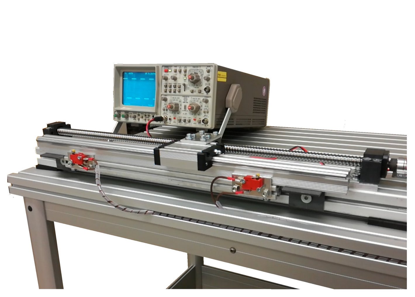
The structure of the experimental setup was specified to the project participants. The most important part of the project task was linking a PC with an Arduino development environment to a stepper motor via an Arduino and a stepper motor output stage.
The project task included familiarizing themselves with and developing a technical understanding of the components of the experimental setup as well as familiarizing themselves with the programming of the Arduino developer board.

Clock signal

The Arduino has the task of generating a clock signal that can be used to control the stepper motor output stage. The Arduino generates the clock signal by constantly switching a digital output on and off again. The duration of the HIGH or LOW state is implemented in the program via delay times in the microsecond range.
Stepper motor output stage

The stepper motor output stage has the task of converting the clock signal at the pulse input into the current pattern for the coils of the stepper motor. Each pulse at the pulse input generates a motor step of 1.8° (200 steps for full rotation).
In addition, the output stage offers the option of switching from full step to microstep. In this case, the stepper motor requires e.g. 800 pulses for a full rotation. This allows the motor to run more smoothly and quietly, but at the same time results in a slight loss of torque.
Video 2 - Der Motor verfährt mit Beschleunigungsrampe
The motor is initially run at the maximum speed that can be achieved from a standstill. The clock frequency at which the stepper motor output stage is controlled is then increased further. The clock frequency can be increased further until the falling torque curve of the stepper motor no longer permits a further increase at higher speeds.