

Planetary gearset

Planetary gearboxes (also known as epicyclic gearboxes) consist of an outer ring gear, several movable planetary gears, and a central sun gear. This makes it possible to achieve up to six different gear ratios in a compact single gearbox. Examples of applications include wind turbine gearboxes, automotive automatic transmissions, and various other industrial gearboxes. The different gear ratios can be tested using the demonstrator shown here. [3]
Quick guide for trying it out right away (“up” means pulling the corresponding locking pin upward and then turning it until it clicks into place; “down” means doing the opposite):
Worm gear
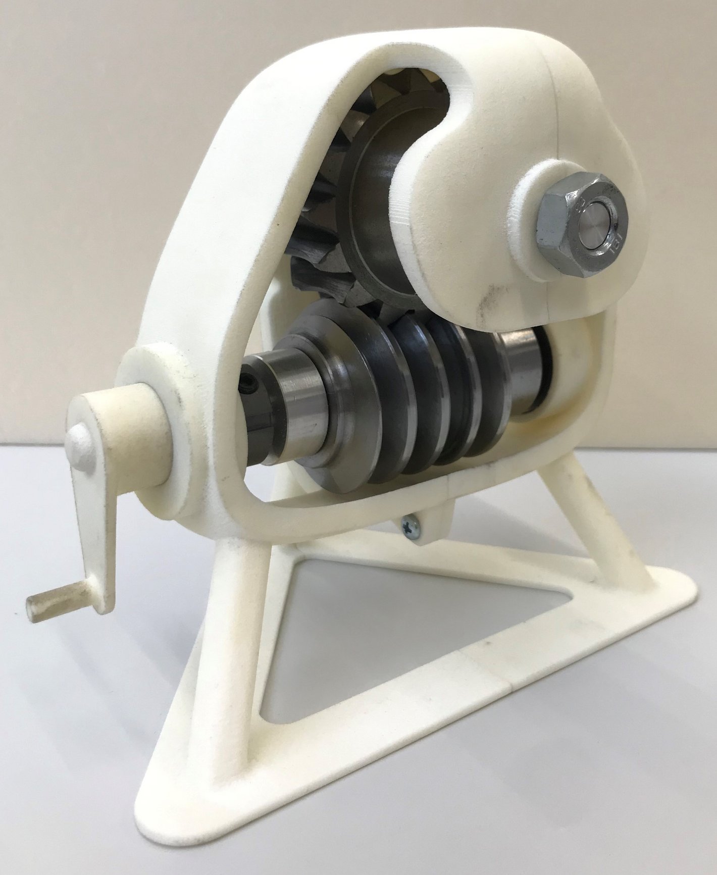
A characteristic feature of a worm gear—and one that can also be seen in the demonstration model on display—is the crossing axes of the so-called “worm” (driven by a crank in the demonstration model) and the “worm wheel.” A major distinguishing feature compared to, for example, a helical-bevel gear set is the nature of the contact. Instead of contacting each other at a single point, the worm and worm wheel make contact along lines within an engagement zone, thereby helping to dampen vibration during operation. Another advantage is the lower contact pressure compared to spur gears.
Application examples: elevators, winches, steering gears in vehicles (high gear ratios at high power levels/drive speeds) [3]
Try it out: Simply turn the crank on the demonstrator and observe the different rotational speeds.
Detailed View of Involute Gears
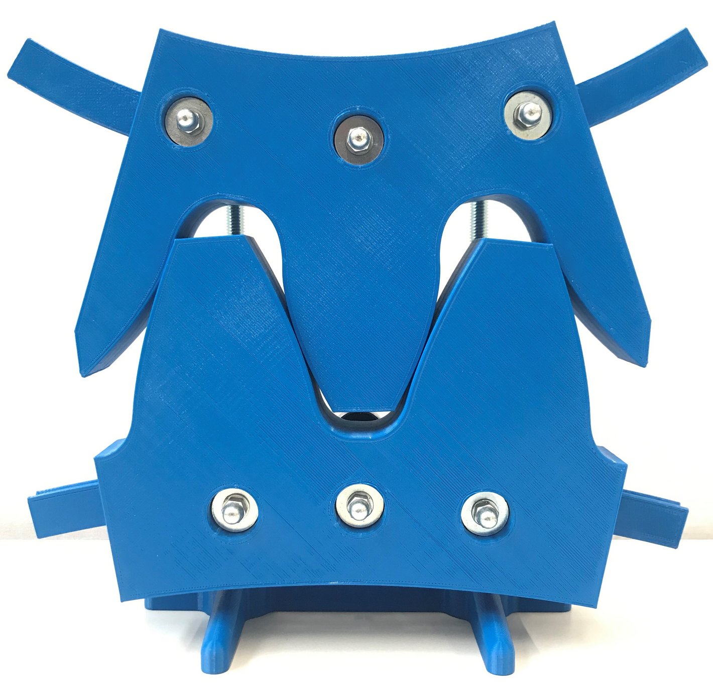
Also on display is a detailed view of the involute gearing of a spur gear. Visitors can use this model to experiment for themselves with how the point of contact moves while there is no contact between the tooth flanks below the pitch circle.
Try it out: Simply move one of the two gears slightly to the left or right.
This page provides an overview of the gearboxes on display in Laboratory T52 at the University of Applied Sciences Emden/Leer. It begins with a general overview of what gearboxes are, how they work, and the different types that exist.
This is followed by a closer look at the gearboxes on display in the glass case, along with background information.
The highlight of the exhibition, the ZF transmission, is also explained in more detail in a separate section.
General Information About Gearboxes
What is a transmission?
A transmission is used to change or adjust kinematic parameters such as rotational speed and linear velocity. In addition, a transmission can be used to bridge or influence shaft distances and angular positions, as well as to control the torque curve. [3]
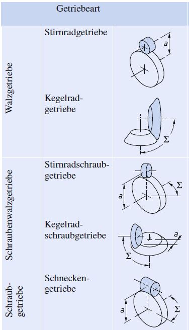
What types of gearboxes are there?
A selection of gearboxes is shown in the following table. In principle, transmissions can be classified according to their operating principles (hydraulic, pneumatic, mechanical), the ability to change rotational speed (shiftable, non-shiftable, continuously variable), or the type of gear ratio (equal, unequal). Due to the wide range of applications and designs, only a small selection is presented on these pages. [3]
The highlight of the exhibition

Next to the glass display case is a 5HP19 FL transmission from ZF Getriebe GmbH, on permanent loan.
Fact sheet
- Automatic transmission for front-wheel-drive vehicles
- Designed for longitudinally mounted engines
- Integrated differential
- 5 forward gears + reverse gear
- Max. 169 kW transmissible engine power
- Max. 310 Nm transmissible torque
- Used in BMW, Audi, VW, Porsche [2]
The transmission designation is structured as follows:
- 5 = Number of forward gears
- H = Hydrodynamic starting element (torque converter clutch)
- P = planetary gearset
- F = Front-wheel drive
- L = Longitudinally mounted engine [2]
A detailed explanation of the transmission and the power flows, as well as a description of the individual components (such as the clutches and shifting elements), can be found in printed form on the transmission itself.
Structure
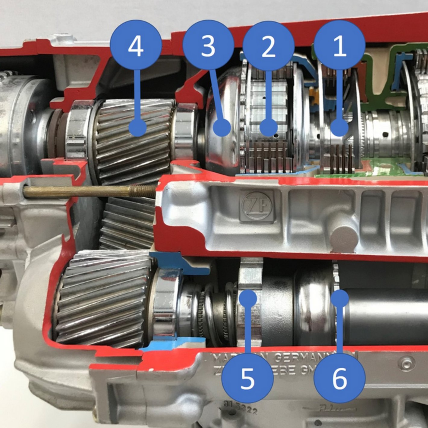
Linker Teil
- Lamellenbremse G
- Lamellenkupplung F
- Einfacher Planetentrieb (verdeckt)
- Stirntrieb für Frontantrieb
- Parksperrenrad
- Geberrad für Drehzahlfühler
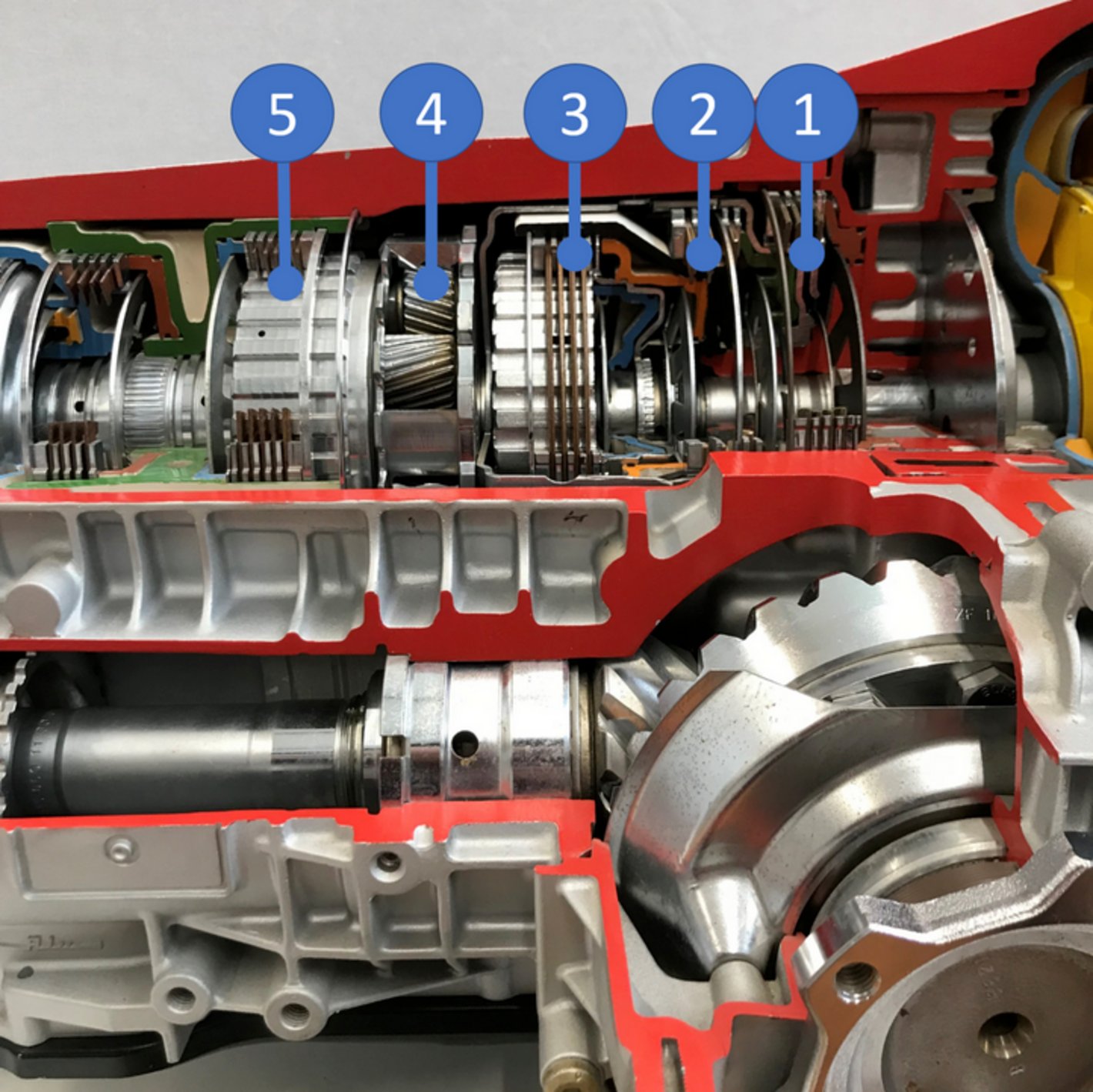
Mittlerer Teil
- Lamellenbremse C
- Lamellenkupplung B
- Lamellenkupplung E
- Ravigneauxsatz (Plantengetriebe mit zwei Sonnenrädern)
- Freilauf und Lamellenbremse
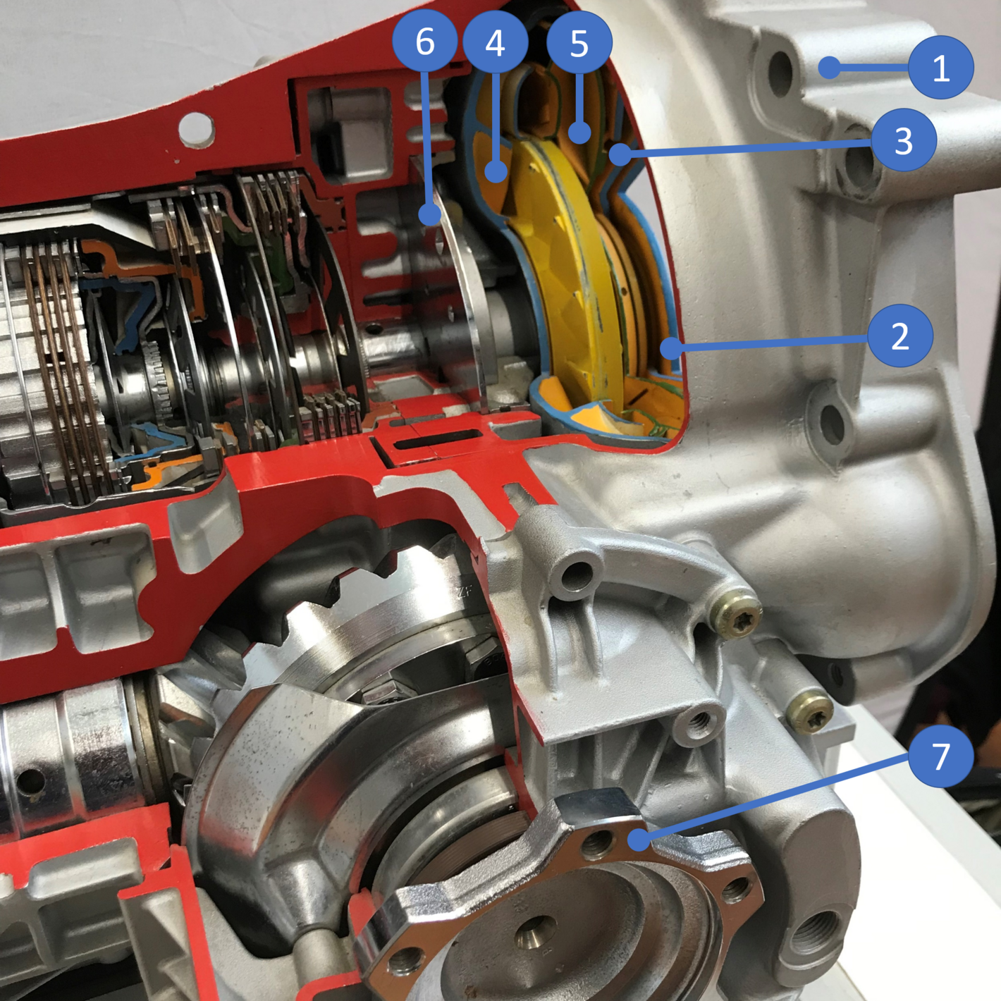
Rechter Teil
- Flansch Motor (Antriebsflansch)
- Wandlerdeckel
- Wandlerkolben
- Pumpenrad
- Turbinenrad
- Ölpumpe
Die gelb eingefärbten Teile gehören zur sog. Wandlerkupplung
Bibliography
[1] Wittel, H., Muhs, D., Jannasch, D., Voßiek, J. (2013). Roloff/Matek Machine Elements. Wiesbaden: Springer Fachmedien, 2013.
[2] ZF Friedrichshafen AG. ZF 5 HP 19 FL Automatic Transmission for Front-Wheel-Drive Passenger Cars, available at: https://www.taligentx.com/passat/maintenance/atfchange/ZF5HP19FL_Literature.pdf (accessed October 20, 2022).
[3] Wittel, H., Spura, C., Jannasch, D. (2021). Roloff/Matek Machine Elements. Wiesbaden: Springer Vieweg, 2021
[4] Markus Isgro (EMAG GmbH & Co. KG). How Do Differential Gears Work? 3 Questions – 3 Answers, available at: https://www.emag.com/blog/1579-2/(accessed on November 10, 2022)
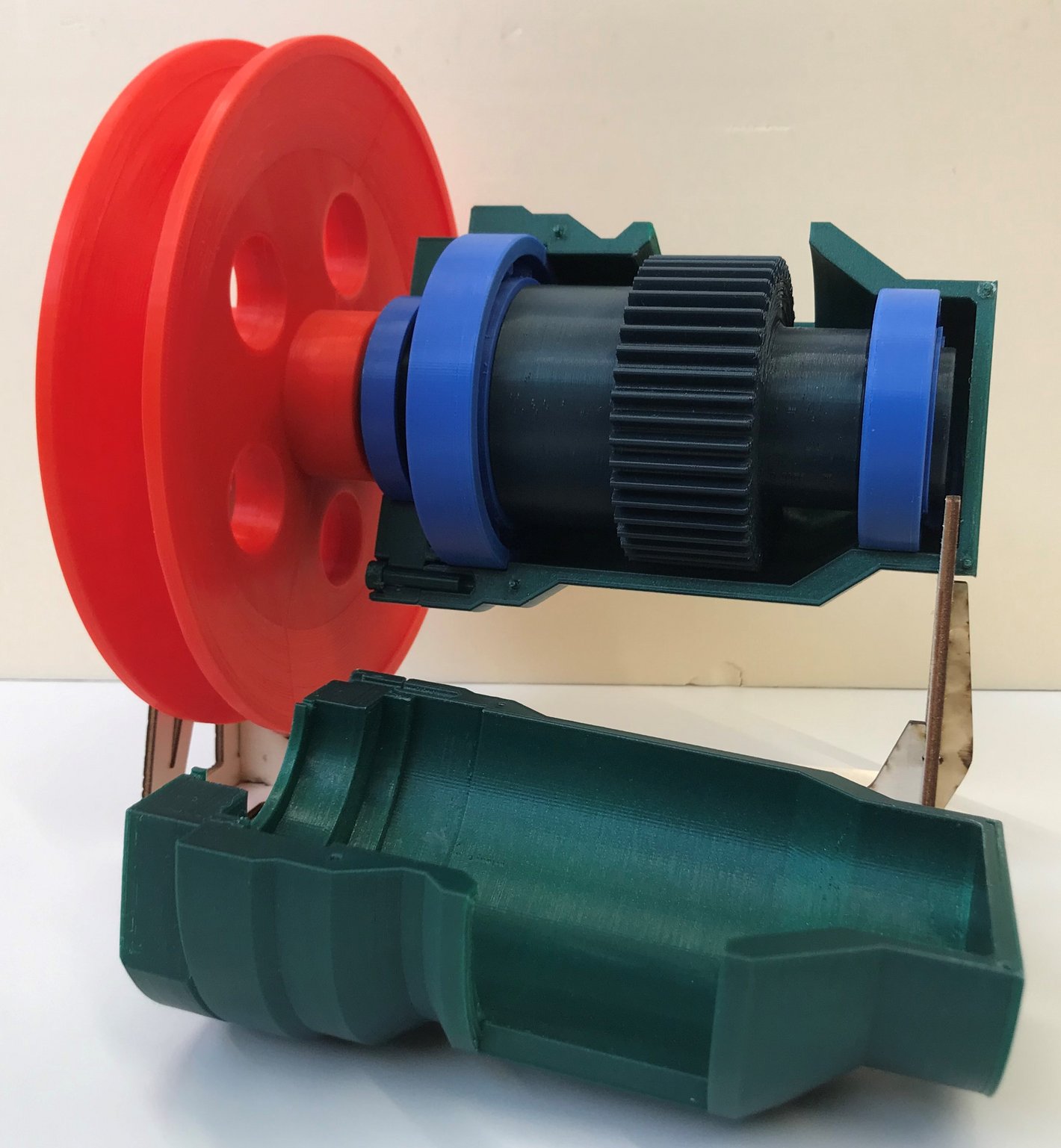
Tensioning Gearbox
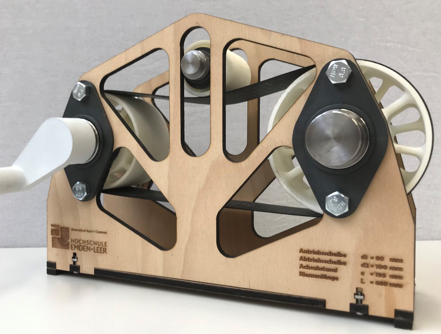
This on-display demonstrator of a traction drive allows observers to see the effects of crowned pulleys on the belt, its centering, and the idler and driven sections during operation. The tensioner pulley on the belt can be loaded with weights during actual operation to adjust the belt’s pretension. The pretensioning device will be retrofitted at a later date.
Try it out: By turning the crank alternately (clockwise/counterclockwise), you can simulate the transition between the loaded and unloaded sections. Determine whether the belt’s pretension should be applied during the loaded or unloaded section.
Behind and next to the demonstrator are a display panel and a binder containing various belt samples. The samples from the ring binder can be removed individually.
Differential Gearbox
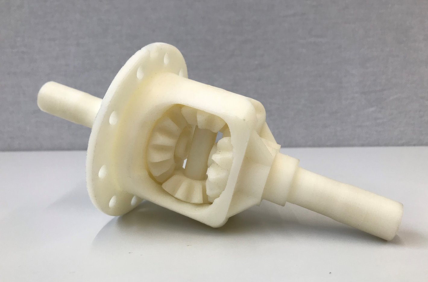
The demonstrator shown here represents a differential or balancing gear. One of the best-known examples of its application is the automobile: When driving around a curve, the wheel on the outside of the curve must travel a longer distance and therefore rotate at a higher speed. The differential gear distributes the torque from the drive shaft to both drive wheels. This is achieved using several bevel gears (in the demonstrator: balancing gears and left/right axle shafts).
An explanation of the application example mentioned can be seen in this video. [4]
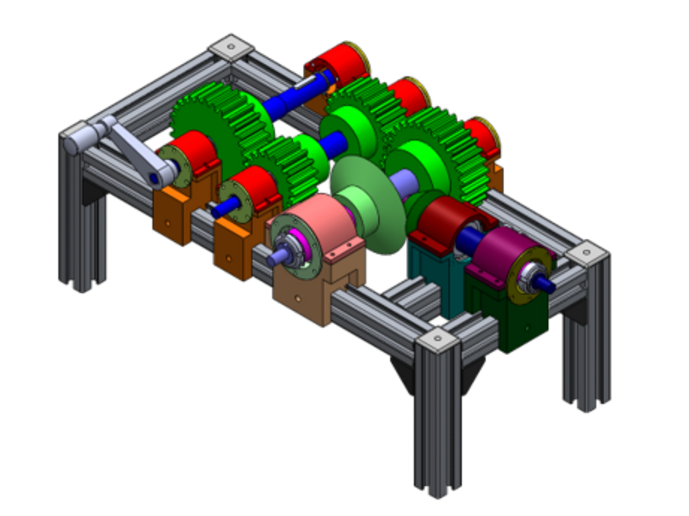
Information Sheet
File with a brief explanation of the demonstrator and exercises to try on your own
Installation Instructions
Instructions for Complete Assembly of the Demonstrator
Search