

Shaft-Hub Connections
What are axles and shafts used for?
Axles and shafts are used to support a wide variety of machine parts. Depending on their intended use, they come in different designs; the most common are rotationally symmetric bodies. In these cases, the length is generally significantly greater than the diameter.
What are the differences between axles and shafts?
| Axles | Shafts |
stationary or rotating | rotating |
Transmits bending moments, transverse forces, and longitudinal forces | also transmits torsional moments |
| Application examples: Supporting impellers, pulleys | Application examples: Supporting gears, pulleys, couplings Special applications: Crankshafts (drive technology), flexible shafts for low torques up to approx. 15 Nm (medical technology, tachometers) |
[5] [6]
Screws
What is a screw?
Screws are the most commonly used machine elements and the most versatile fasteners.
What types of screws are there?
Screws are classified according to their function into fastening screws, motion screws, sealing screws, adjusting screws, measuring screws, clamping screws, etc. The intended use of a screw can usually be deduced from its designation.
In the case of fastening screws, the rotational movement of the screw causes the components to be clamped together. Motion screws convert rotational movements into linear movements. Sealing screws are used to close inlet and outlet openings. Adjustment screws are used to align devices and instruments, as well as for adjustments in valve control systems.
Transverse and Longitudinal Pin Connections
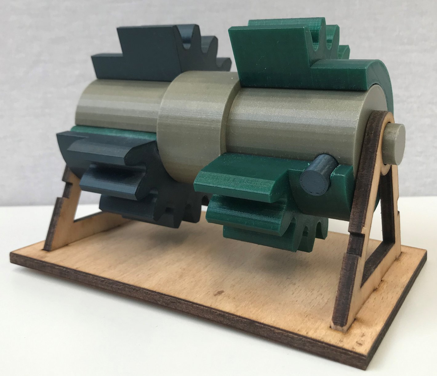
This demonstrator shows two spur gears on a shaft in a cross-sectional view. A transverse pin is used to connect the green spur gear to the shaft, while a longitudinal pin is used to connect the gray spur gear to the shaft. A pin connection can transmit small, shock-free torques. [4]
Keyways


One possible machine element for a shaft-hub connection is the key. The top image shows several keys conforming to DIN 6885, Form A, measuring 4 x 4 x 10 mm. The lower image shows a key conforming to DIN 6885, Form A, measuring 12 x 8 x 56 mm, and a disc spring conforming to DIN 6888, measuring 6 x 9 mm.
Keyways can connect a shaft, for example, to a pulley or a gear. They are primarily used for single-sided torque. As shown in the images, there are various shapes of keyways with different applications. [6]
Types of Threads

The type of thread is determined by several characteristics: the profile shape (e.g., triangular and trapezoidal), the direction of the screw’s threads (left- or right-handed), the pitch, and the number of threads (single- or multi-start). The common thread types are: [1]
- a) and b) Metric ISO threads
- c) Pipe threads
- d) Metric ISO trapezoidal thread
- e) Metric serrated thread
- f) Round thread
Hex head screw with nut

The first exhibit shown is a hex head screw with a washer, a self-locking nut (with a blue plastic ring), and a spring washer (slightly deformed). When the self-locking nut is tightened, the plastic ring deforms in such a way that it prevents the nut from being unscrewed. The spring washer is also intended to prevent or make it more difficult for the screw connection to loosen on its own. The standards for spring washers have since been withdrawn, as they cannot provide sufficient locking effectiveness for screws in higher strength classes. [6]
Expansion screw

The second exhibit shown is an expansion screw. It is characterized by its thinner shank. If the screw and the components to be clamped are made of different materials, a change in temperature will cause them to expand at different rates, resulting in a change in the clamping force. An expansion screw can compensate for this to a certain extent. Expansion screws are also used under high dynamic loads (e.g., in the cylinder head of an internal combustion engine) because they possess greater elastic compliance, thereby improving long-term durability. [6]
Screw Collection
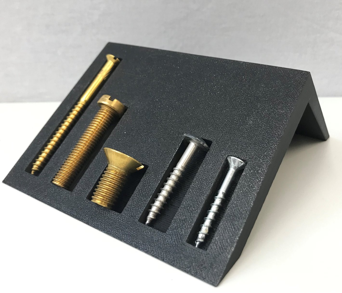
Self-tapping screws are also on display. These screws cut their own threads as they are screwed into the base material. Most of these screws have tapered tips, but there are also self-tapping screws with flat tips. They can be used for sheet metal, plastics, and wood. [2]
The following screws are on display:
- A: Pan-head wood screw with slotted drive – DIN 95, brass – M5 x 70 mm
- B: Cylinder head screw with slotted drive – DIN 84, brass – M8 x 40 mm
- C: Countersunk screw with slotted drive – DIN 963, brass – M10 x 20 mm
- D: Flat-round-head facade screw TX20 RAL 7012 (basalt gray) – stainless steel – 4.8 x 38 mm
- E: Countersunk facade screw - stainless steel 4 x 30 mm
The brass screws on display (A, B, C) are particularly eye-catching thanks to their golden appearance, which depends on their zinc content. Brass screws are typically used as wood screws and are therefore also installed in wooden boats. These boats should not be used in saltwater, as brass provides only limited corrosion protection due to its nickel content. Another possible application is model making, since brass is easy to solder. [3]
Self-locking screw lock
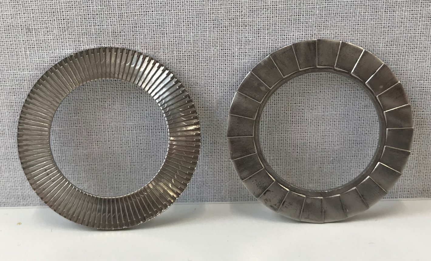
On display is a self-locking bolt lock from Nord-Lock in size M10. It is designed to prevent the bolted joint from loosening on its own. To achieve this, the two washers interlock via their serrated surfaces (keyways). They are installed under the bolt head or, additionally, under the nut. The outer surface of the wedge-locking washer has radial ribs that form a positive fit with the mating surface when the bolt is tightened. [6]
Machine Components Exhibition
Welcome!
On this page of the Laboratory for Machine Elements, you will find further information about the machine elements on display in Lab T52. The current website was created as part of a technical project and serves as an interactive supplement to the on-site exhibition.
The contact persons are Prof. Dr.-Ing. Kathrin Ottink and Dr.-Ing. Thomas Ebel. You can find their contact information here.

The exhibition and this page are organized into the following sections:
- Transmissions
- Clutches
- Shaft-Hub Connections
- Screws
- Bearings
Due to the volume of information, the sections on gearboxes, couplings, and bearings can each be found on separate subpages.
Bibliography
[1] Wittel, H., Muhs, D., Jannasch, D., Voßiek, J. (2013). Roloff/Matek Machine Elements. Wiesbaden: Springer Fachmedien, 2013.
[2] CELO Befestigungssysteme GmbH. “What’s the Difference Between Self-Tapping and Self-Drilling Screws?”, available at: https://www.celofixings.de/content/287-unterschiede-selbstschneidende-und-selbstbohrende-schrauben (accessed October 21, 2022).
[3] Theo Schrauben Shop GmbH. Screw Materials—What Materials Are Available?, at: https://www.theo-schrauben.de/blog/schraubenmaterial-welche-materialien-gibt-es/ (accessed October 21, 2022).
[4] Ottink, Kathrin (2022). Lecture on Machine Elements, Shaft-Hub Connections (Chapter 6)
[5] Ottink, Kathrin (2022). Lecture on Machine Elements, Axles and Shafts (Chapter 2)
[6] Wittel, H., Spura, C., Jannasch, D. (2021). Roloff/Matek Machine Elements. Wiesbaden: Springer Vieweg, 2021
Search