

General Information About Couplings
What is a coupling?
A coupling is a machine component used to transmit rotational energy between two shafts or between a shaft and a rotating component mounted in a fixed position. Depending on the application, it creates a rigid, elastic, movable, or detachable connection. In addition, there are couplings with a switching function that engage and disengage torque transmission. [1]
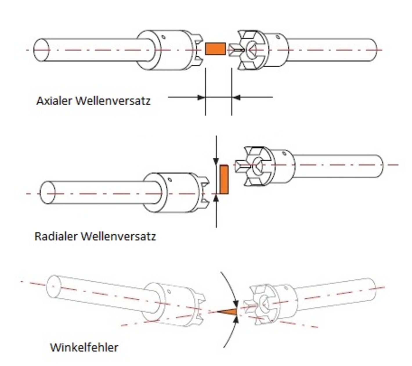
Couplings can also serve a compensating function to accommodate, as shown in the diagrams, axial and radial shaft misalignment (also known as longitudinal and transverse misalignment), as well as angular misalignment. These misalignments can have various causes: Longitudinal displacements can result from thermal expansion or armature displacement (in electric machines), whereas transverse and angular displacements are caused by installation inaccuracies, warping of machine frames, foundation settlement, or elastic mounting. Angular errors can also result from torque spikes and torsional vibrations. These torque spikes can be mitigated or dampened by a coupling. [2]
What types of couplings are there?
Clutches are divided into two main groups based on their shifting function: shiftable and non-shiftable. In terms of power transmission, they are also classified as friction-type, positive-lock, hydrostatic, hydrodynamic, or electromagnetic. With form-fit couplings, there is no slippage between the coupling halves, and the transmissible torque is limited by the strength of the transmission components. In contrast, with friction-type couplings, slippage is possible during engagement and under overload conditions, and the transmissible torque depends on the friction conditions and the contact force between the parts to be coupled. Finally, slip is constantly present during the operation of hydrostatic and hydrodynamic couplings. It increases with the torque to be transmitted. [1, 2]
This page provides an overview of the couplings on display in Laboratory T52 at the University of Applied Sciences Emden/Leer. It begins with a general overview of what couplings are, how they work, and the different types available.
This is followed by a closer look at the exhibits in the glass display case, along with background information.
Exhibits
Lamellenkupplungen
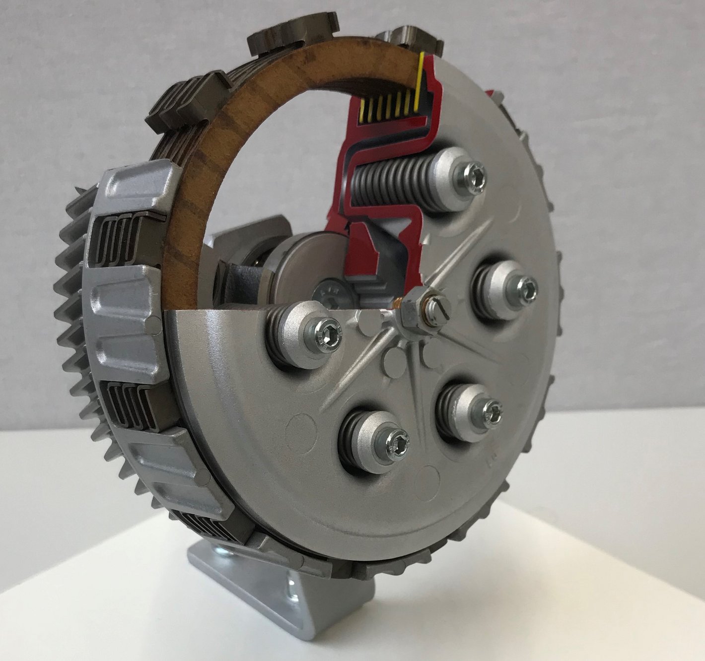
The first image shows a multi-disc clutch. Its cage contains several inner and outer discs, which allow high torques to be transmitted despite the small diameter. The coil springs visible in the cutaway model generate the contact force between the discs. [3]
Disc couplings consist of several friction discs connected in series and alternately linked to the coupling halves, which increases the number of friction surfaces. This, in turn, increases the transmissible torque proportionally. [1]
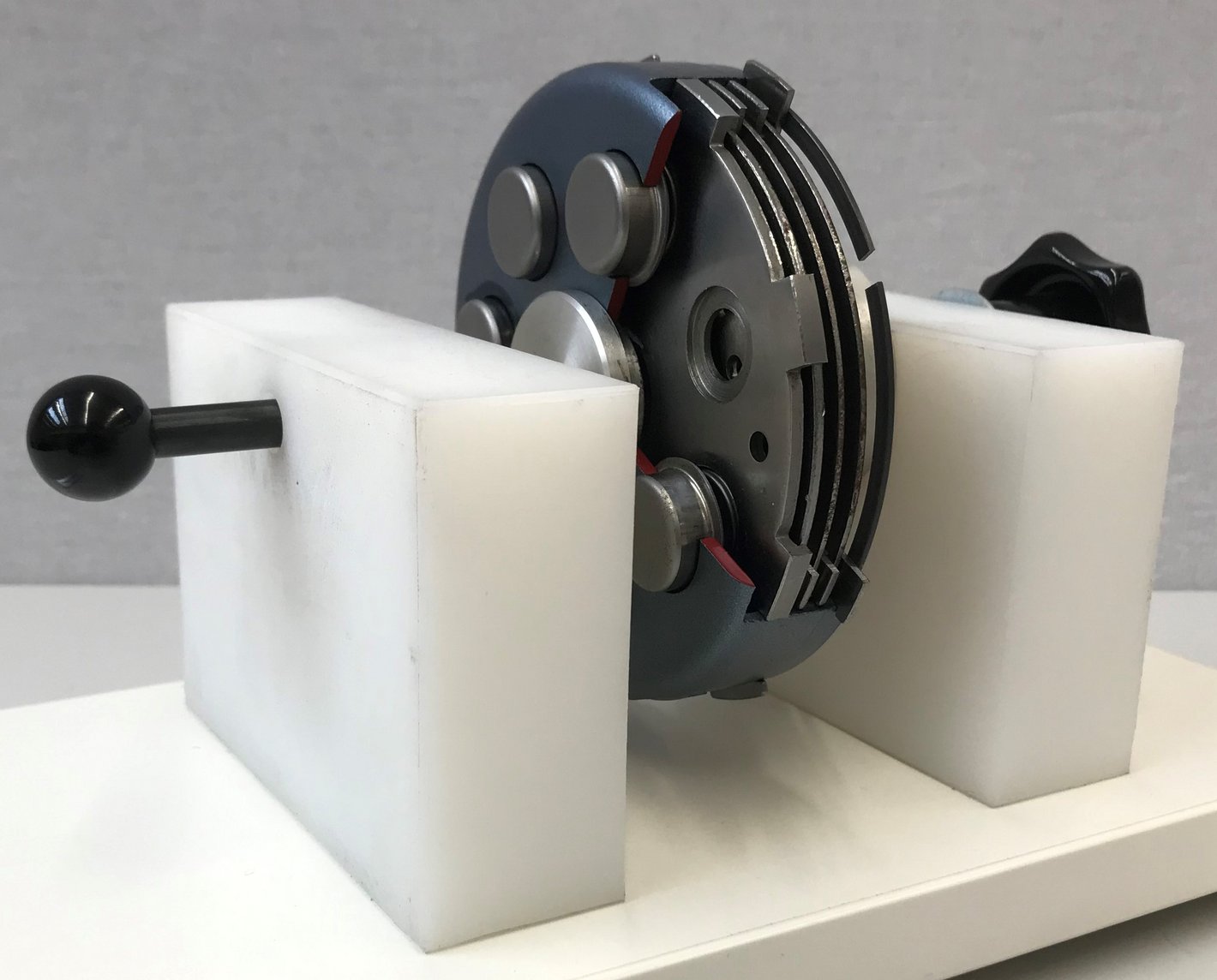
With the second coupling on display, you can try for yourself how coupling affects the flow of force. [4]
Instructions:
- Rotate the clutch while it is engaged by turning the star-shaped knob → Power flow
- Engage the clutch by pressing the round knob → Clutch is now disengaged
- Rotate the clutch while it is disengaged by turning the star-shaped knob → Power flow interrupted
Note: Disengaging the clutch can be a bit stiff and requires a little patience and finesse.
Claw coupling
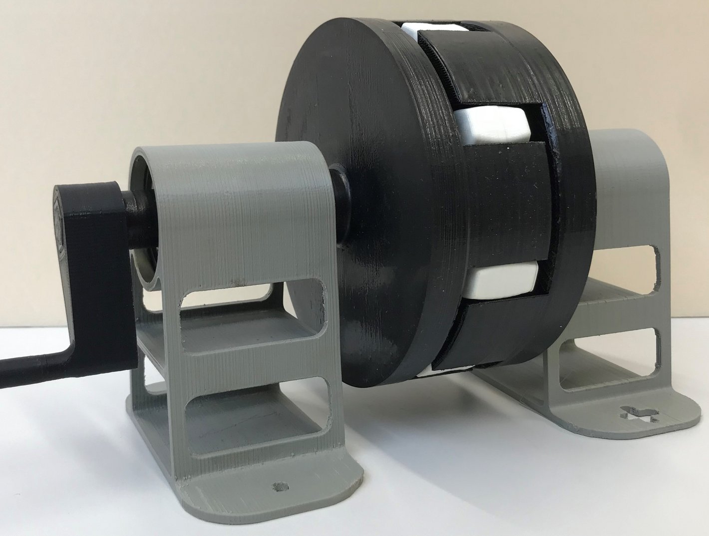
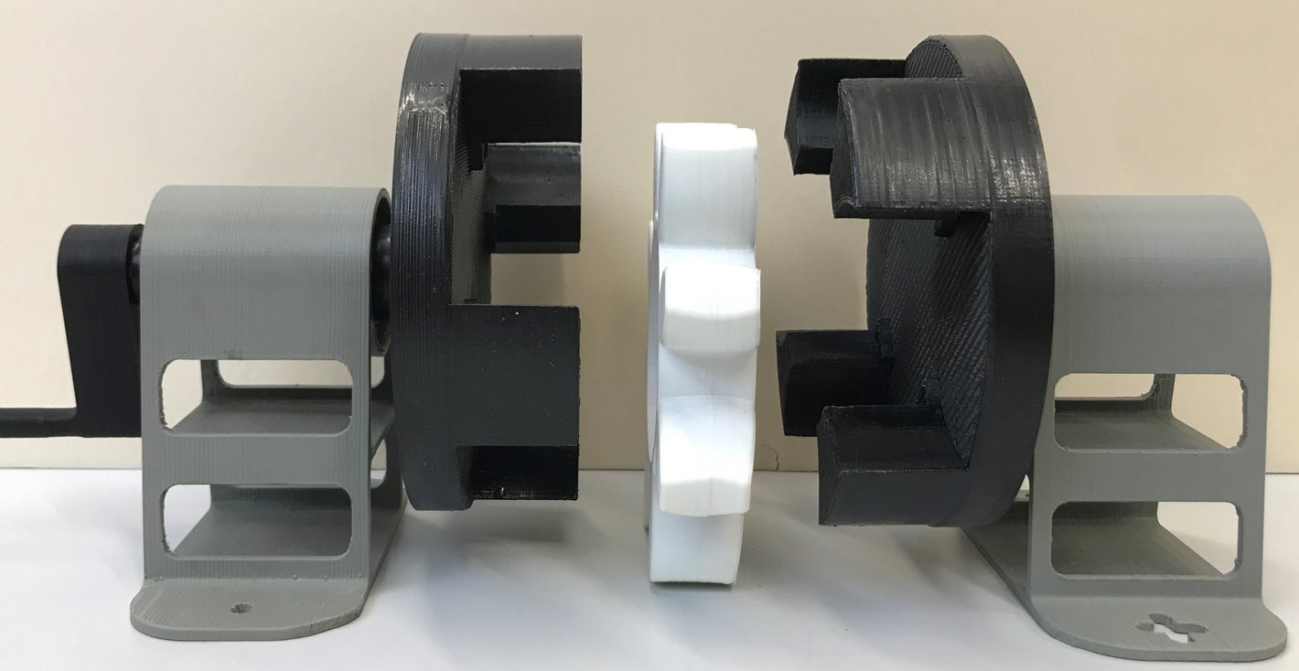
This demonstrator shows an elastic claw coupling. It is a non-switchable coupling and consists of two coupling halves with so-called concave claws. In the spaces between them, these claws engage with a star-shaped insert made of Vulkolan, whose teeth are spherical in shape. This serves to reduce or prevent edge pressure during shaft misalignment. The elasticity helps prevent start-up shocks and compensates for axial misalignment.
Examples of applications include: fans, centrifugal pumps, hoists. [7]
Try it out: Pull the two coupling halves apart and bend the elastic star slightly.
Tooth Coupling
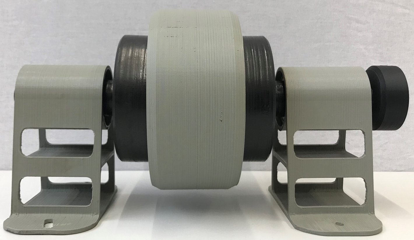
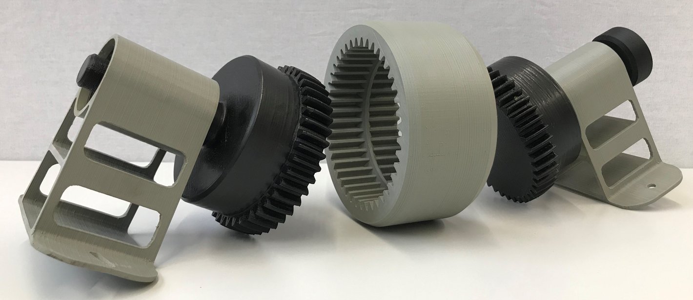
The gear coupling shown consists of a sleeve and two shafts with gears (hubs). The tooth flanks of the hubs are curved and crowned, while the tooth profile of the sleeve is straight. This allows for axial displacement and also compensates for angular misalignment. A gear coupling can transmit high torques and high rotational speeds. [7]
Try it out: Simply pull the two hubs apart and remove the sleeve. Once reassembled, the coupling can be rotated using the washer.
Magnetic coupling
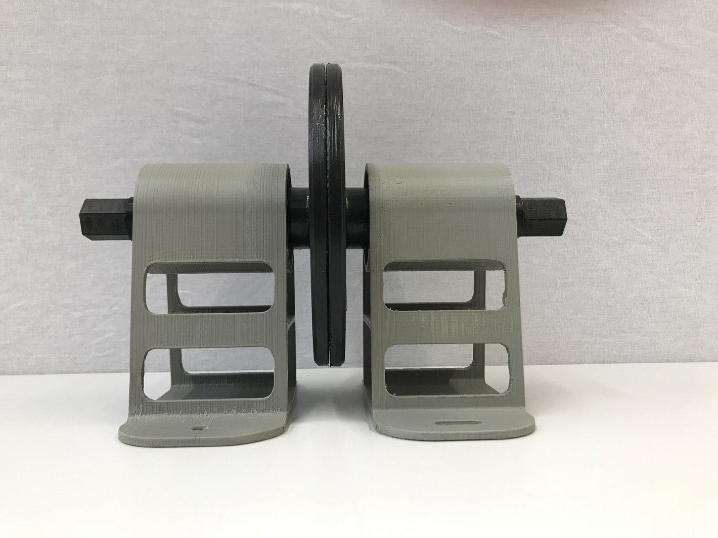
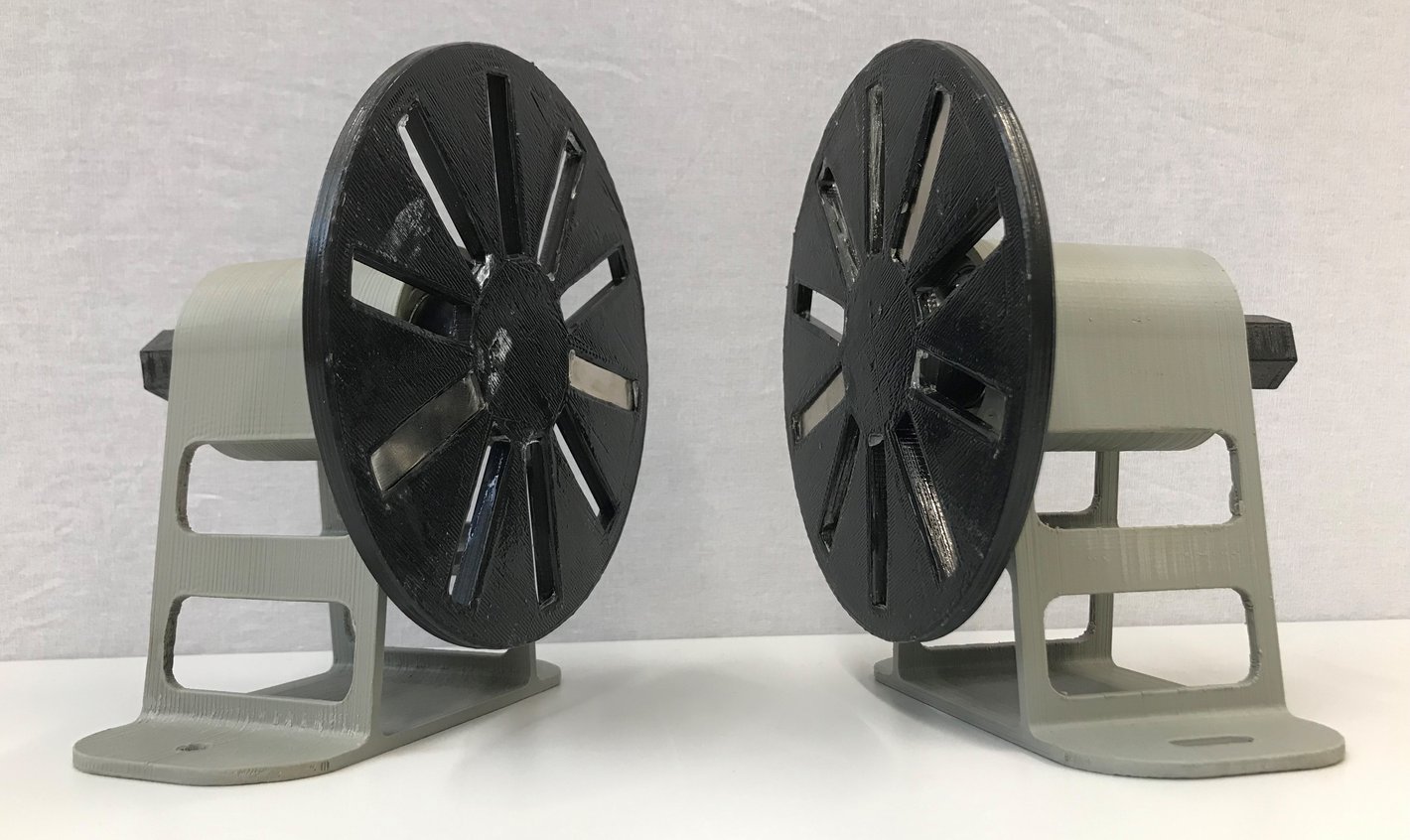
The demonstrator shown here illustrates how a magnetic coupling works. The two coupling discs have recesses in which magnets are mounted. Since this is a demonstration model, only a few magnets are installed. This allows the discs to be separated by pulling the shafts apart (just give it a try!).
Magnetic couplings offer the advantage that force can be transmitted through a wall, for example. This is used, for instance, in special pumps for the chemical industry that require a particularly tight seal. In such cases, there is no need to route a shaft through the housing. [6]
Centrifugal clutch
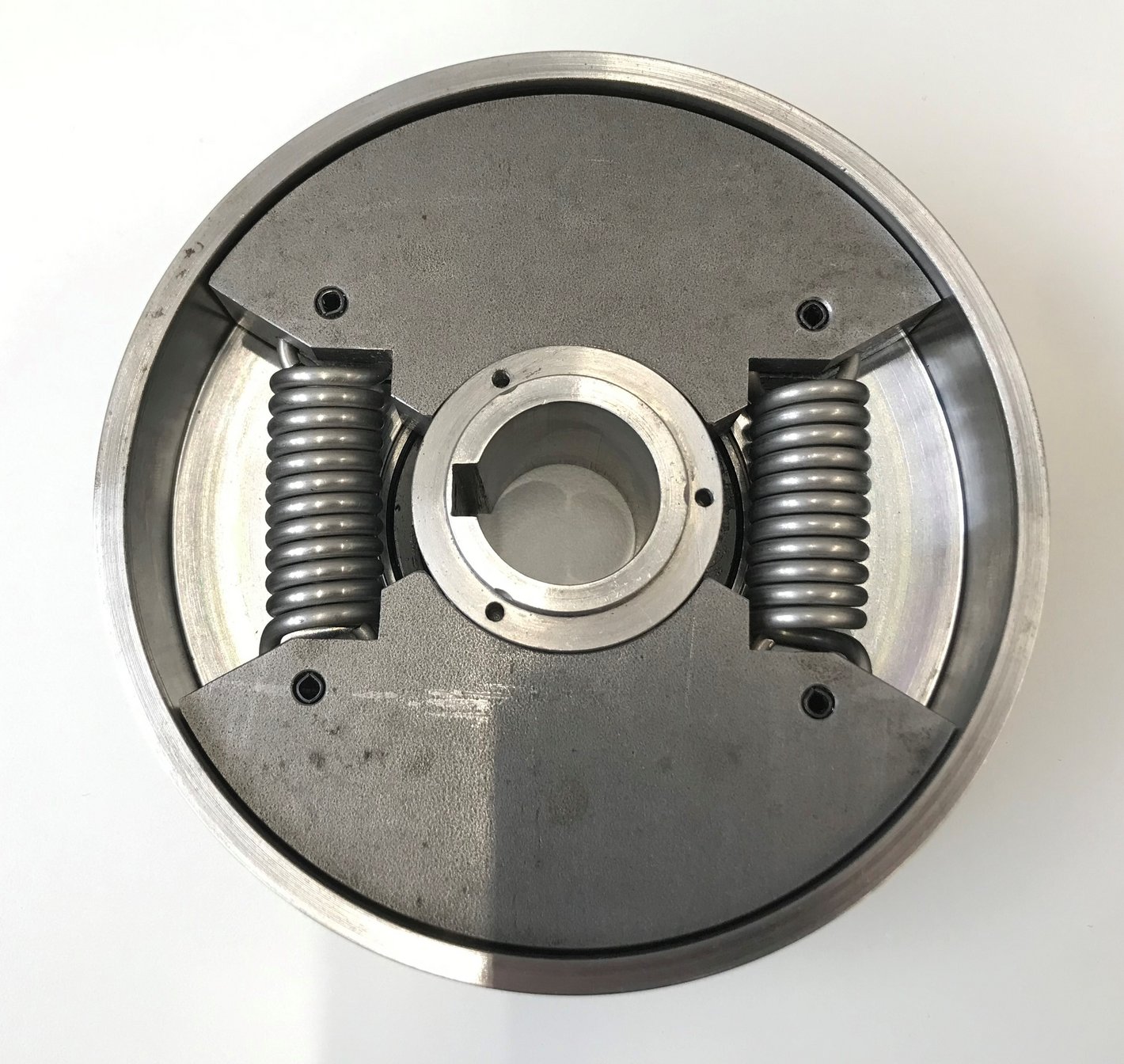
On display in the showcase is a so-called speed-activated jaw-type centrifugal clutch. At a speed defined by its design, this type of clutch engages automatically (centrifugal control). A drive shaft drives the interior of the centrifugal clutch (two radially movable jaws). The centrifugal forces generated (depending on the rotational speed) press the jaws against the output-side outer ring. Torque is then transmitted through friction. [7]
Applications include: drives for centrifuges, cement mills, heavy vehicles, etc. (anywhere where high starting torque is required due to large masses that need to be accelerated). [6]
Bibliography
[1] Wittel, H., Muhs, D., Jannasch, D., Voßiek, J. (2013). Roloff/Matek Machine Elements. Wiesbaden: Springer Fachmedien, 2013.
[2] Künne, B. (2008). Köhler/Rögnitz Machine Parts 2. Wiesbaden: Vieweg + Teubner Verlag.
[3] Hako-Lehrmittel. Multi-disc Clutch, available at: https://hako-lehrmittel.de/de/produktkatalog/lamellenkupplung/ (accessed on October 19, 2022).
[4] Hako-Lehrmittel. Multi-disc clutch, available at: https://hako-lehrmittel.de/de/produktkatalog/lamellenkupplung-2/ (accessed on October 19, 2022).
[5] Ludwig Meister GmbH & Co. KG. Couplings, available at: https://www.ludwigmeister.de/produkte/kupplungen/39119 (accessed October 20, 2022).
[6] Ottink, Kathrin (2022). Lecture on Machine Elements: Couplings
[7] Wittel, H., Spura, C., Jannasch, D. (2021). Roloff/Matek Machine Elements. Wiesbaden: Springer Vieweg, 2021
Search